What is a Structured Cabling Network System and the 6 Essential Components?
Structured Cabling Systems, Also Known as Modern or Organized Cabling Systems, Support Telecommunications
Kelsey Young, Copywriter and Media Specialist
5 Min Read
Businesses are more global than ever relying on cloud services and computing services. With cloud computing, the need for new telecommunication connections within data centers has dramatically increased and will continue to do so.
Therefore, businesses should not ignore investing in modern telecommunication cabling systems.
Thanks to a structured cabling network system, the process is easier than ever. Structured cabling takes out the guess work so companies can rest assured their certified technicians can easily find a non-disruptive solution when adding a new connection to their infrastructure system.
But what is structured cabling? In simplistic terms, structured cabling is a set of standards outlined by The American National Standards Institute and Telecommunications Industry Assocation (ANSI/TIA) for setting up all points of a residential or commercial cabling distribution system. It is a solution, standardizing how data communications flow within a building, be it business, government, or educational building.

ANSI/TIA-568, the first structured cabling standards, was released in 1991. It included Generic Telecommunications Cabling for Customer Premises (C.0) and Commercial Building Telecommunications Infrastructure Standard (C.1). Naturally, as technology advances the structured cabling standards have been updated.
The components of a cabling system are all made to specific standards for electrical transmission, resistance, cable lengths, connectors, and cable fabrication. These standards simply the process for companies and technicians.
All of this is to say structured cabling simplifies installation, maintenance, and troubleshooting of wiring problems associated with the transmission of data within the cabling infrastructure.
Why is this even important? A carrier or provider only needs to run their part of the connection to the entry point of the building. Afterward, their involvement in the cabling process is complete and it is the responsibility of the data center manager or IT services provider to make sure connections go where they need to.
The standard of structured cabling replaces the individual client cables with a high-volume multi-service infrastructure backbone which connects the telco or carrier service to multiple predetermined distribution areas within the data center.

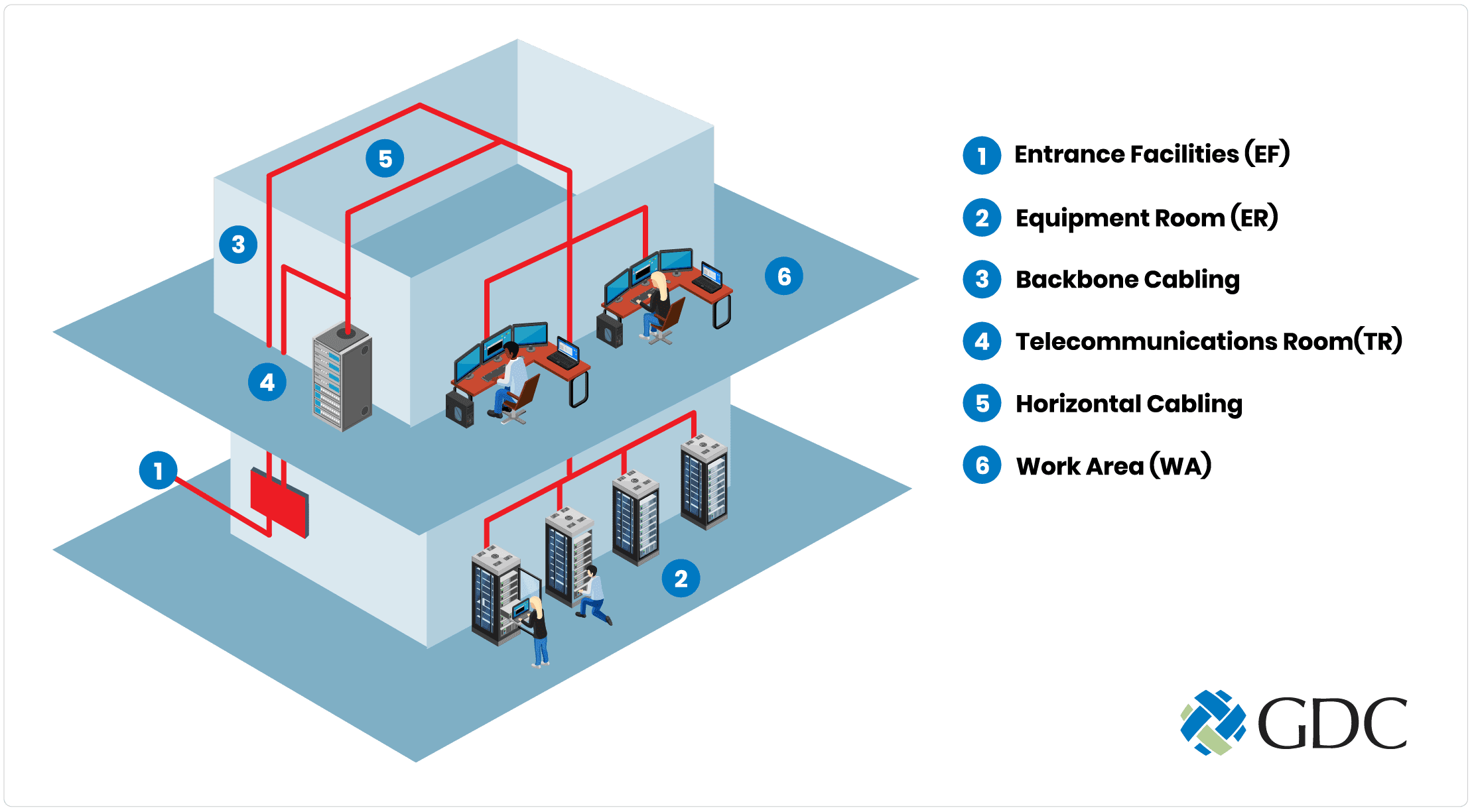
The 6 Essential Subsystem Components of a Structured Cabling System Network
Entrance Facilities (EF)
Entrance Facilities (EF) is defined as the point where the local service provider or private network brings the outside connection to the building.
The network connection needs to pass through an opening in the exterior wall by a conduit. From this point, the cabling goes directly to the room where the other devices and network connections are deployed. The cables needed for this connection are usually the responsibility of the carrier and not the business owner’s responsibility. However, it is important to note that this is where the carrier’s responsibility ends. The rest of the cables will be the user’s responsibility.
Equipment Room (ER)
Equipment Room (ER) is defined as the area where the entrance cabling connects to the building’s internal wiring infrastructure.
This is the backbone for the building. It houses cabling, horizontal cabling, and intermediate cabling. The ER may also house other network necessities. Some ERs may also be climate controlled to protect the equipment housed inside.
Backbone Cabling
Backbone Cabling, also referred to as Riser Cabling, is the imperative vertical cabling linking EF and ER telecommunications to each floor in the building.
There are three subsystems within backbone cabling. Each subsystem refers to a set of cables that run between specific points.
Cabling subsystem 2 specifically refers to the cabling between a horizontal cross-connect (HC) and intermediate cross-connect (IC).
While cabling subsystem 3 refers to the cabling between an IC and the main cross-connect. Cabling subsystem 1 is horizontal cabling. It is a large subsystem. Therefore, it has its own section below.
Telecommunications Room (TR) and Telecommunication Enclosure (TE)
A Telecommuncations Room or Enclosure is, or should be, an environmentally controlled, dedicated area or room. A TE could also be a specific enclosure within a larger TR. There could be multiple TR/TE spaces in a building, usually one on each floor.
Think of these rooms as a cable hub. Hardware in these spaces terminate backbone cabling (including horizontal cabling). It is also where local cables, also known as jumper cords or patch cords are used on patch panels to cross-connect different cables.
If additional resources are needed, IC and Main cross-connect (MC) can also be installed in the TR/TE.
Horizontal Cabling (Cabling Subsystem 1)
Horizontal Cabling is a cabling system which moves communication resources on a horizontal plane.
Most commonly, a horizontal cable will run from a user’s device to the closet TR/TE. Standards dictate a horizontal cable can run no longer than 295 feet between the TE and the user’s station, regardless of cable type.
Horizontal cabling includes the cable, connectors, patch panels, jumpers, and patch cords in the TR/TE. They may also include multiuser telecommunications outlet assemblies and consolidation points to connect multiple devices or cables in a single connector.
Work Area (WA)
A Work Area is the area from a connector, or jack, in a wall outlet to a user device which uses a cable.
The work area encompasses all components between the faceplate and Ethernet based device. This includes the patch cable between the faceplate and Ethernet device. Each work area is served by a telecommunication wiring closet typically on the same floor.
The work area is the final destination for the structured cabling system.
The Benefits of a Structured Cabling Network System
Below are a few of the benefits of using a structured cabling system.

Eliminating the lengthy process of evaluation and quoting. Cabling companies should have a catalog of services, cables, and other fixed costs.

Standardized pricing across companies.

No hidden costs from faults or troubleshooting. The entire infrastructure should be warranted and certified.

Protection for the current cable pathways. Since there is no overflow of multiple cables, companies can rest assured there will be no unexpected cost when an overflowing pathway collapses.

Improved reliability of service. Companies can have the confidence and peace of mind that their systems and platforms are not in danger of downtime.

Faster installation time. Installation time for a cross connect goes from 10+ days to less than 1 day.

Changes to the existing service carrier are simplified because they only need to provide the connection to the EF.
Implement Structured Cabling Systems for Your Business with GDC
As a premier IT infrastructure implementation and management provider, GDC certified engineers can help you establish and maintain a structured cabling system that delivers cost-savings, future-proofs your business, reduces downtime, and improves productivity.
Have any questions or concerns with your current cabling system? Contact the experts today to request a free consultation.


